Home Automation with ESP32
Build a Humidity-to-Color Display
4-Hour Hardware Camp
by Brendon Thiede
Welcome!
Today you build a real circuit with a real microcontroller…
…and you take it home.
Here's the goal
By the end of camp, this is yours.
Icebreaker
Name one thing in your home you wish was smarter or did something automatically.
Today's Roadmap
| 0:00–0:45 | Welcome + what is home automation? |
| 0:45–1:10 | Meet the hardware |
| 1:10–1:45 | 🔧 Build & upload your first code |
| 1:45–2:00 | ☕ Break |
| 2:00–3:30 | 🔧 Sensor → LED → full project |
| 3:30–3:40 | ☕ Break |
| 3:40–4:00 | 🔧 Make it yours + show & tell |
Most of today is hands-on building.
What Is Home Automation?
Making things in your home sense, decide, and act — without you doing it by hand.
Real Examples
- Smart thermostat (Nest)
- Color-changing lights (Philips Hue)
- Motion-sensor porch lights
- Smart door locks
What do these all have in common?
What Makes Something "Smart"?
Sensor → Logic → Output
Something it can feel → a rule → something it does.
Today's Three Pieces
💧 DHT22 sensor (humidity/temperature)
↓
🧠 ESP32 brain
↓
🔴🟢🔵 RGB LED output
Meet the Hardware
Pick up each part as we talk about it — but don't wire anything yet.
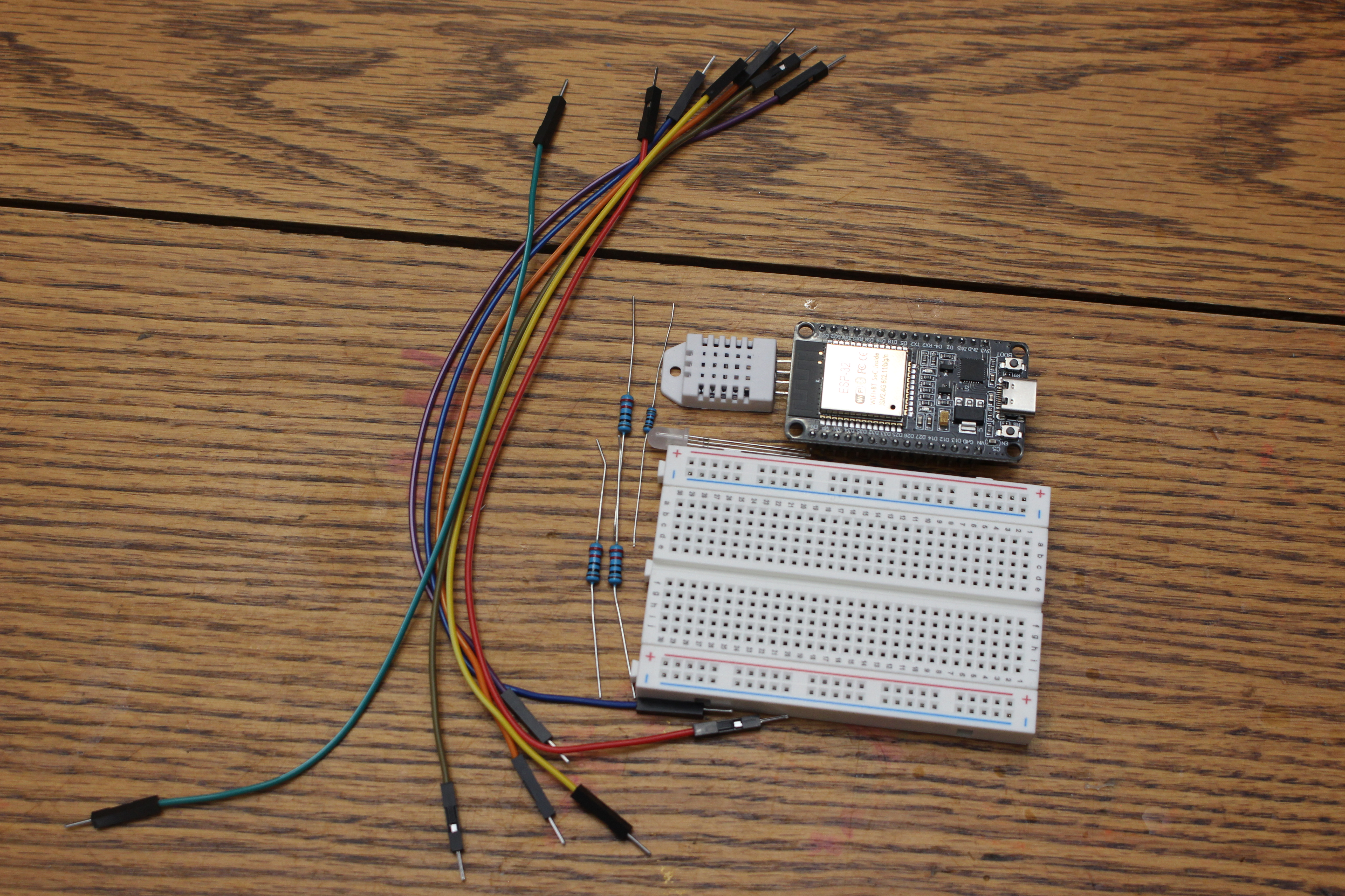
Your Kit
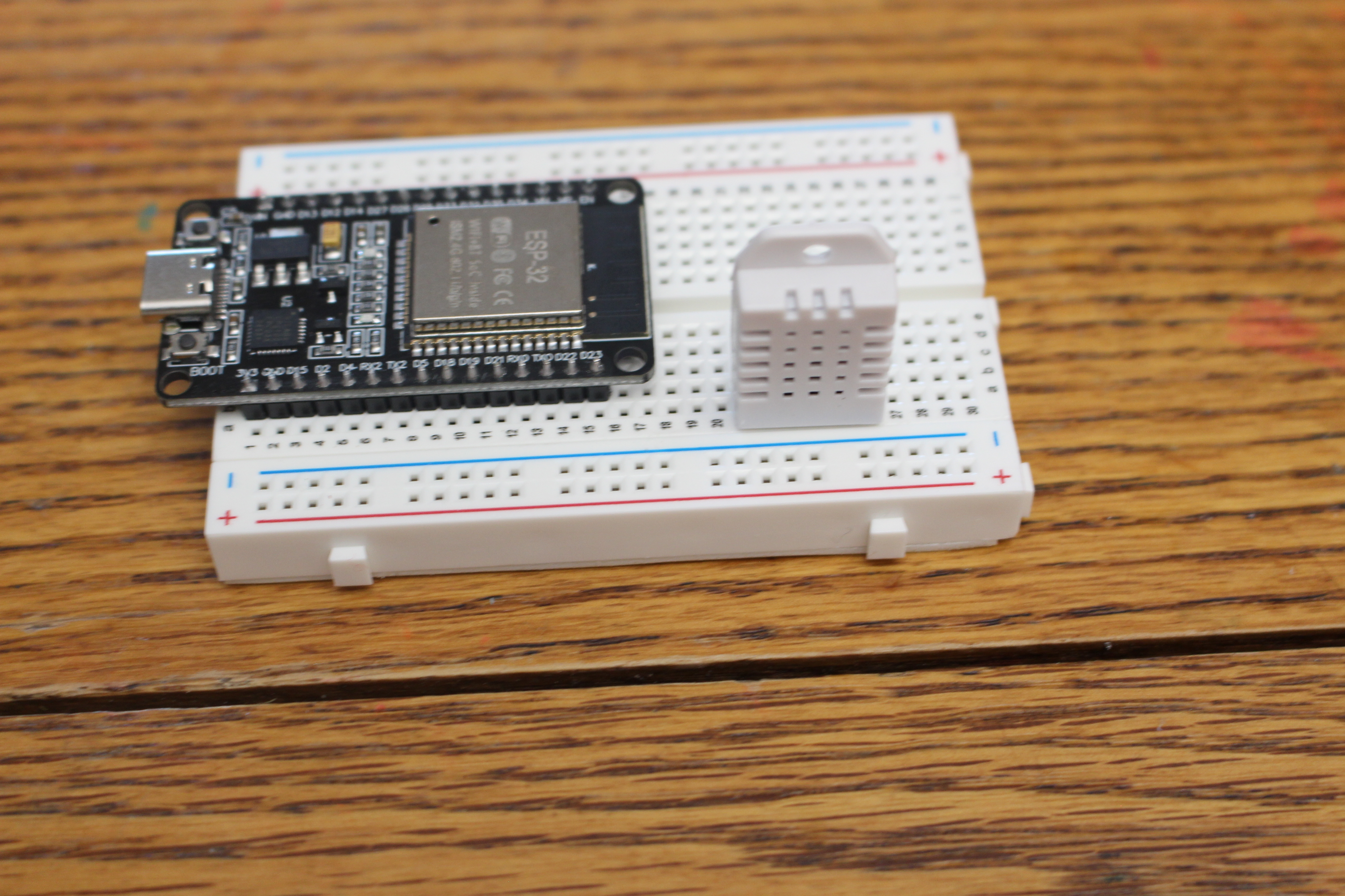
The Breadboard
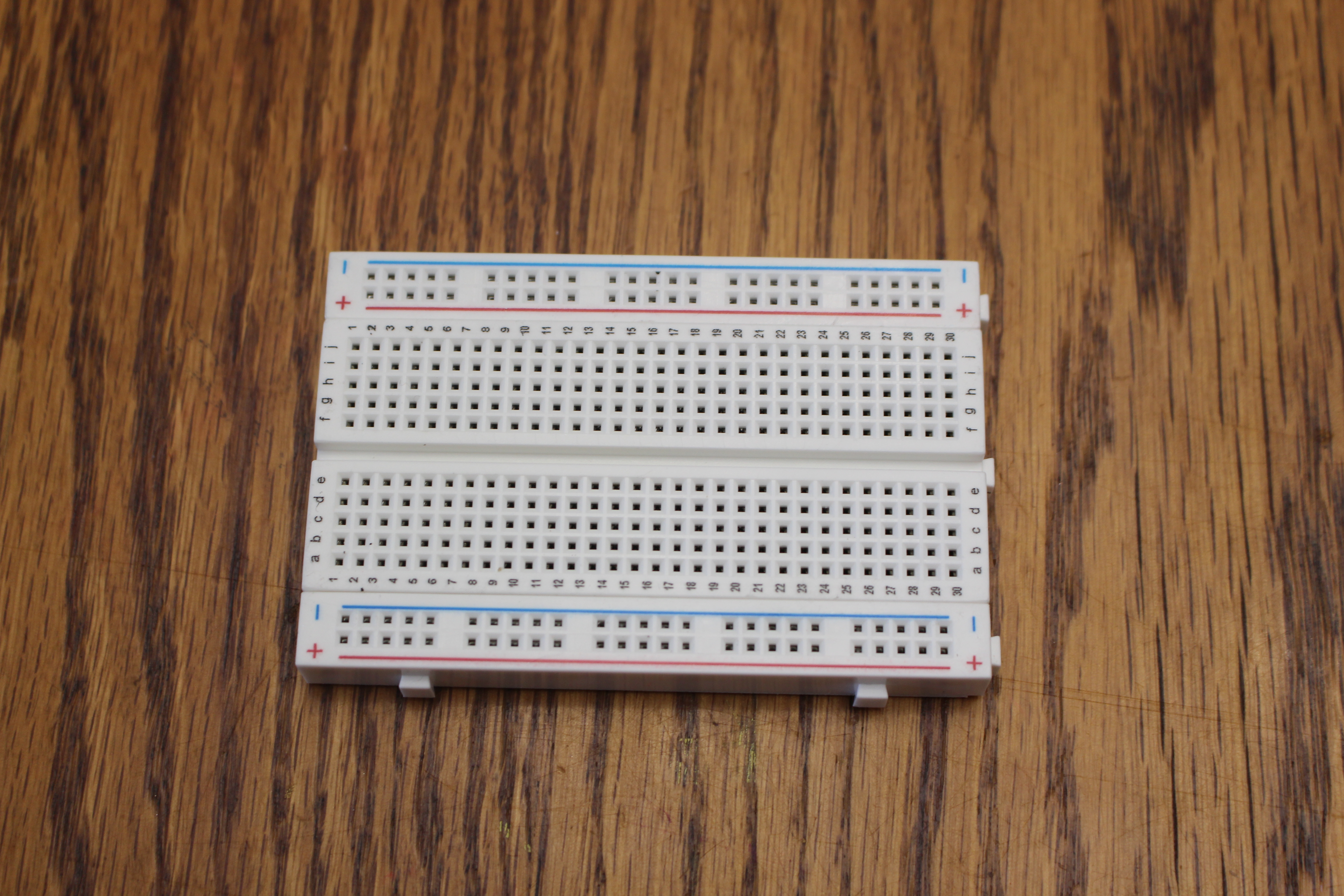
No soldering — parts just push in. The rows secretly connect for you.
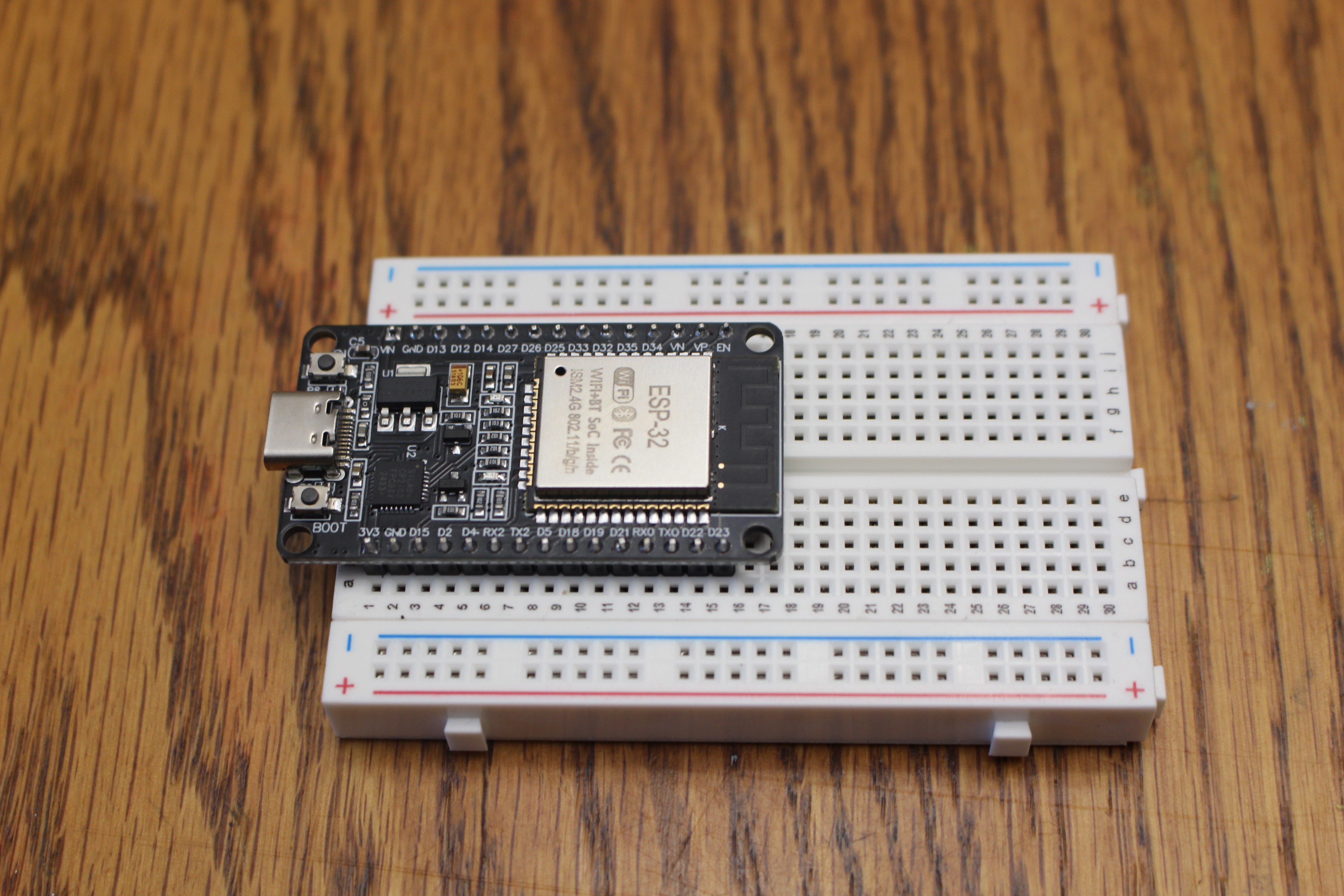
The ESP32 — Our Brain
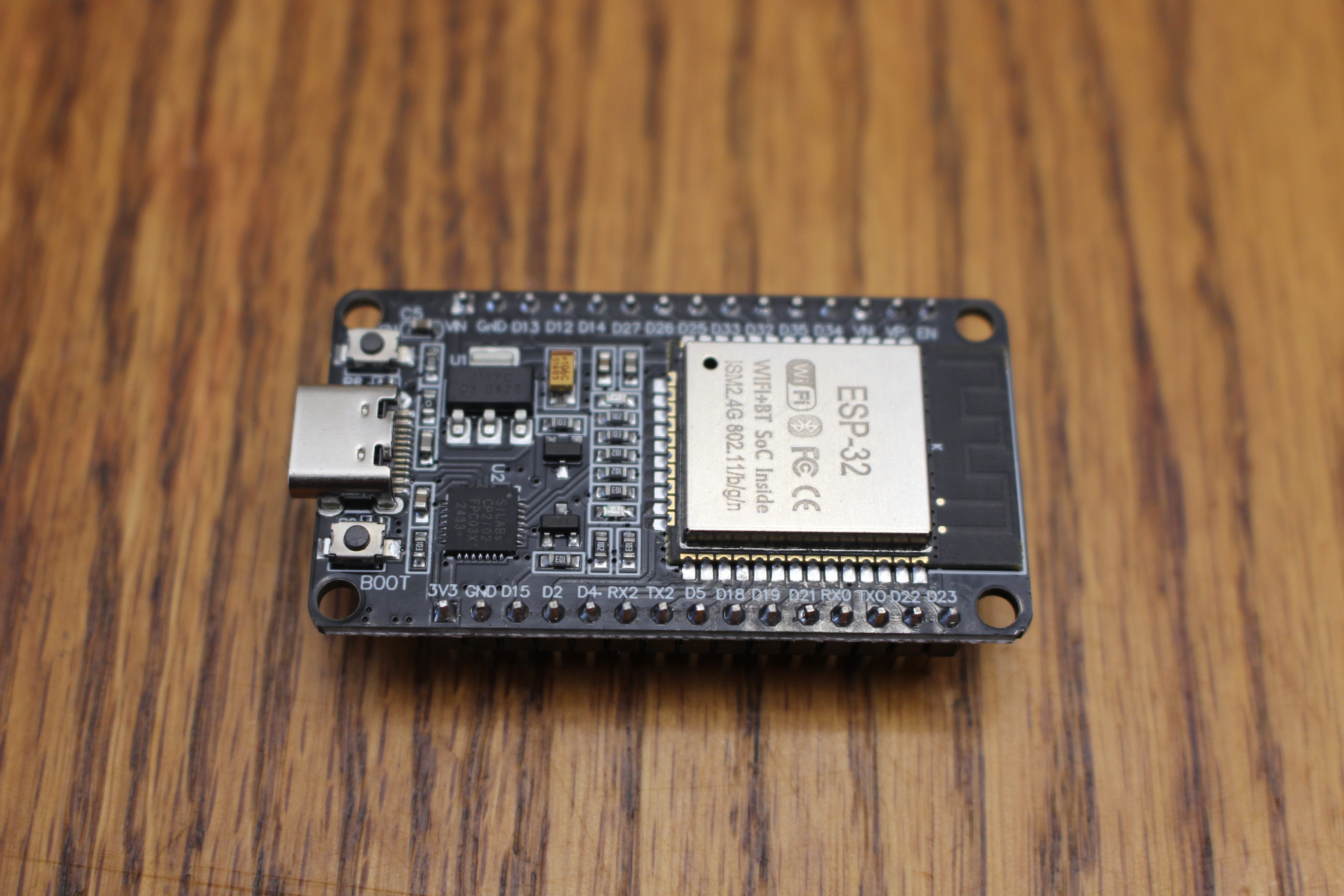
A tiny, cheap, programmable computer — about $6.
The DHT22 — Our Sense of Touch
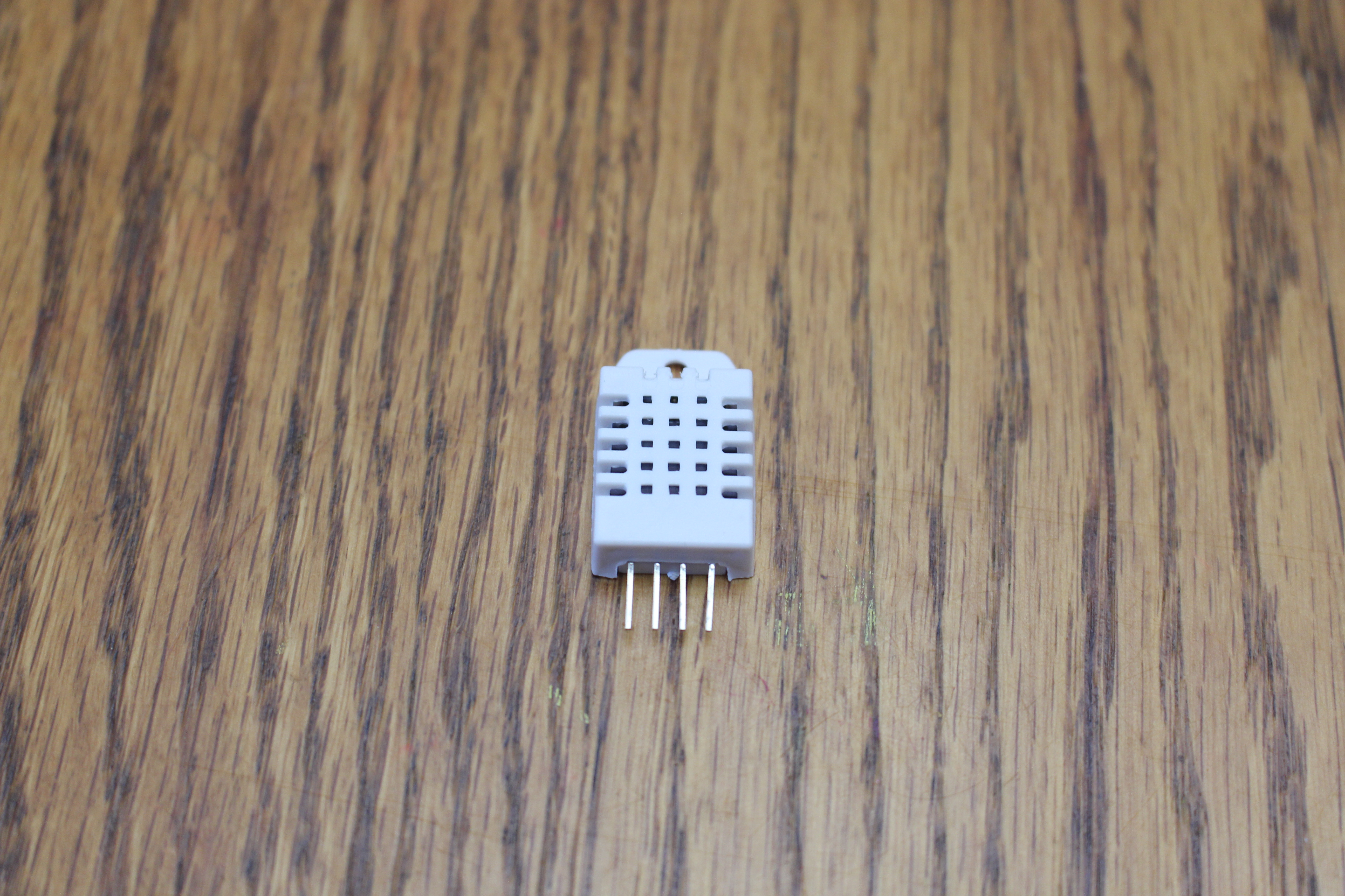
Reads humidity (and temperature too) — breathe on it and the humidity jumps.
The RGB LED — Our Output
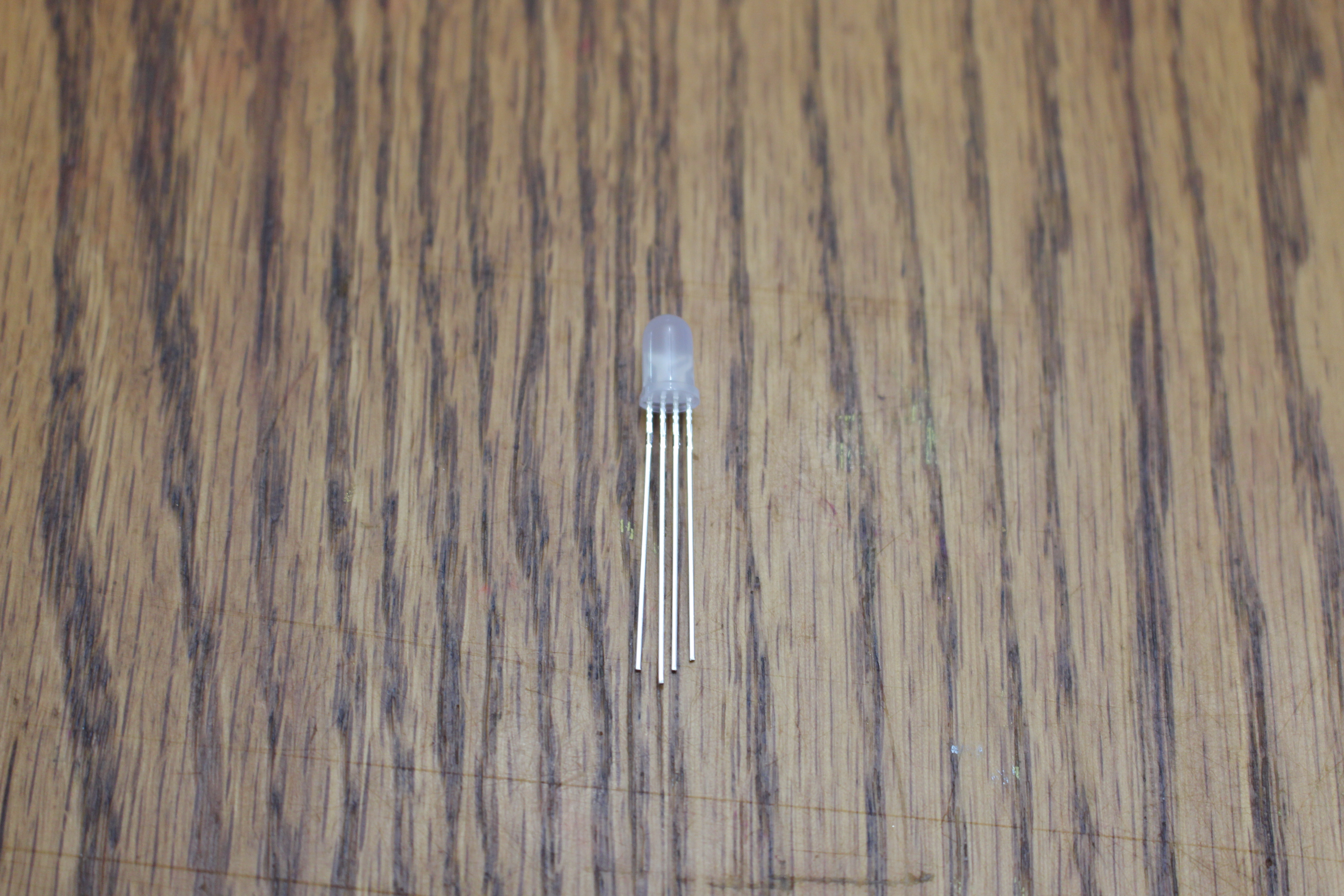
Three colors can be blended. Legs (left to right): Red, GND (longest leg), Green, Blue.
Resistors
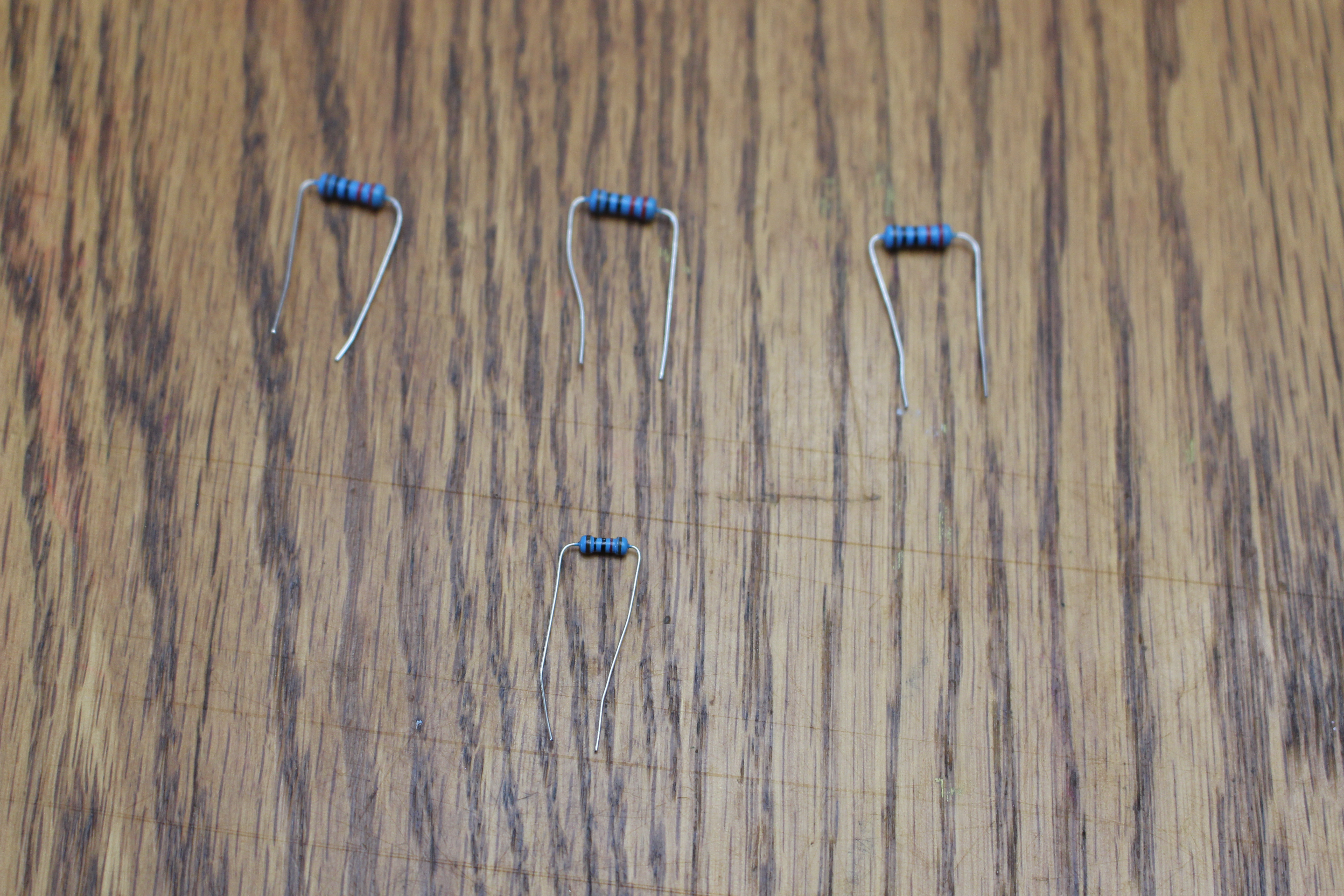
Resistors slow electricity down so we don't burn parts out.
Resistors
- 3 × 220 Ω — one for each LED color
- 1 × 10 kΩ — helps the DHT22 talk clearly
Resistors slow electricity down so we don't burn parts out, decreasing current while increasing voltage.
⚠️ Safety Rules
- Unplug USB before changing wires
- Check your work, then plug in
- Ask if you're unsure. Always.
📋 Quick Quiz!
Checkpoint 1 — Intro & Hardware
Join at learning-check.web.app
Enter the code on the screen.
Phone, tablet, or laptop — whatever you've got.
🔧 Build #1
Seat the board & upload your first code
Step 1 — Seat the ESP32
Step 2 — Plug In
In order to send a program to the ESP32, we need to connect it to our computer via USB using a data cable (not a charging-only cable).
No external wires for this step — the LED we blink is already on the board (GPIO 2).
Step 3 — Open the Project
- Open VS Code → PlatformIO
- Open the
onboard-LED-blinkproject underhome-automation - Peek at
platformio.iniandsrc/main.cpp
The Code
const int LED_PIN = 2;   // the LED already on the board

void setup() {
  pinMode(LED_PIN, OUTPUT);
  Serial.begin(115200);
}

void loop() {
  digitalWrite(LED_PIN, HIGH);   // on
  Serial.println("LED ON");
  delay(500);
  digitalWrite(LED_PIN, LOW);    // off
  Serial.println("LED OFF");
  delay(500);
}
✅ Milestone Check
Everyone's onboard LED is blinking and Serial Monitor scrolls "LED ON / LED OFF".
Stuck? Wrong COM port, missing CP210x driver, or baud rate not 115200.
📋 Quick Quiz!
Checkpoint 2 — Your First Blink
Join at learning-check.web.app
Enter the code on the screen.
Phone, tablet, or laptop — whatever you've got.
☕ Break — 15 min
Stretch, water, walk around.
Leave your board plugged in and happy.
🔧 Build #2
Wire the DHT22 & read the room
Pins We'll Use
| DHT22 pin | Connects to |
|---|---|
| VCC | 3V3 |
| DATA | GPIO 4 + 10 kΩ pull-up to 3V3 |
| NC | leave empty |
| GND | GND |
Wiring Diagram
Wiring Diagram
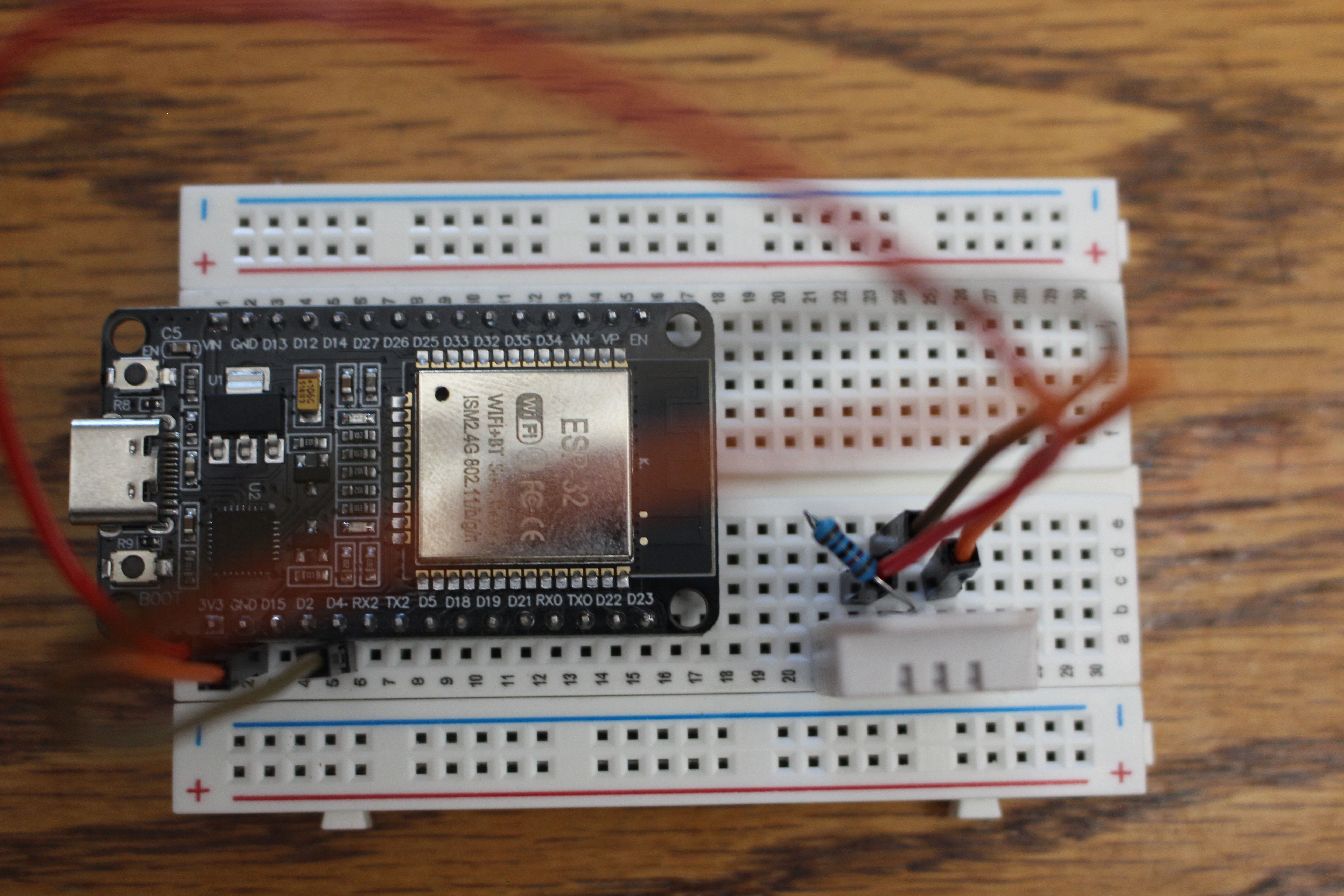
Why the 10 kΩ Resistor?
Our bare DHT22 has no built-in pull-up. Without that 10 kΩ bridge from DATA to 3V3, you'll get read errors.
It keeps the data line "held high" so the sensor's signal is clear.
The Code
#include <DHT.h>

#define DHTPIN 4
#define DHTTYPE DHT22
DHT dht(DHTPIN, DHTTYPE);

void setup() {
  Serial.begin(115200);
  dht.begin();
}

void loop() {
  float humidity = dht.readHumidity();
  float tempC = dht.readTemperature();

  if (isnan(humidity) || isnan(tempC)) {
    Serial.println("Read failed - check wiring!");
    return;
  }
  Serial.print("Humidity: "); Serial.print(humidity);
  Serial.print("%  Temp: "); Serial.print(tempC);
  Serial.println("C");
  delay(2000);
}
✅ Milestone Check
Real humidity & temperature numbers scroll in Serial Monitor.
Breathe on the sensor — watch humidity jump!
📋 Quick Quiz!
Checkpoint 3 — Reading the Room (DHT22)
Join at learning-check.web.app
Enter the code on the screen.
Phone, tablet, or laptop — whatever you've got.
🔧 Build #3
Add the RGB LED & make it glow
Pins We'll Use
| LED leg | Connects to |
|---|---|
| Red | 220 Ω → GPIO 18 |
| Common cathode (longest) | GND |
| Green | 220 Ω → GPIO 19 |
| Blue | 220 Ω → GPIO 23 |
Resistor goes in series with each color leg — never on the cathode/GND leg.
Wiring Diagram
Wiring Diagram
Mixing Color with PWM
const int RED_PIN = 18, GREEN_PIN = 19, BLUE_PIN = 23;

void setColor(int red, int green, int blue) {
  ledcWrite(0, red);     // 0–255 brightness per channel
  ledcWrite(1, green);
  ledcWrite(2, blue);
}

void setup() {
  ledcSetup(0, 5000, 8);   ledcAttachPin(RED_PIN, 0);
  ledcSetup(1, 5000, 8);   ledcAttachPin(GREEN_PIN, 1);
  ledcSetup(2, 5000, 8);   ledcAttachPin(BLUE_PIN, 2);
}
PWM = blinking faster than your eye can see, to fake "half brightness."
Test One Color at a Time
Before mixing — prove each channel works:
setColor(255, 0, 0);  delay(700);   // red only
setColor(0, 255, 0);  delay(700);   // green only
setColor(0, 0, 255);  delay(700);   // blue only
The starter firmware runs this R→G→B self-test on startup for you.
✅ Milestone Check
Red, green, and blue each light up on their own.
Green/blue look dim? That's expected — we can swap them to 150 Ω later.
📋 Quick Quiz!
Checkpoint 4 — Make It Glow (RGB LED)
Join at learning-check.web.app
Enter the code on the screen.
Phone, tablet, or laptop — whatever you've got.
🔧 Build #4
Put it all together
Sensor reading → color logic → glowing LED, in one loop.
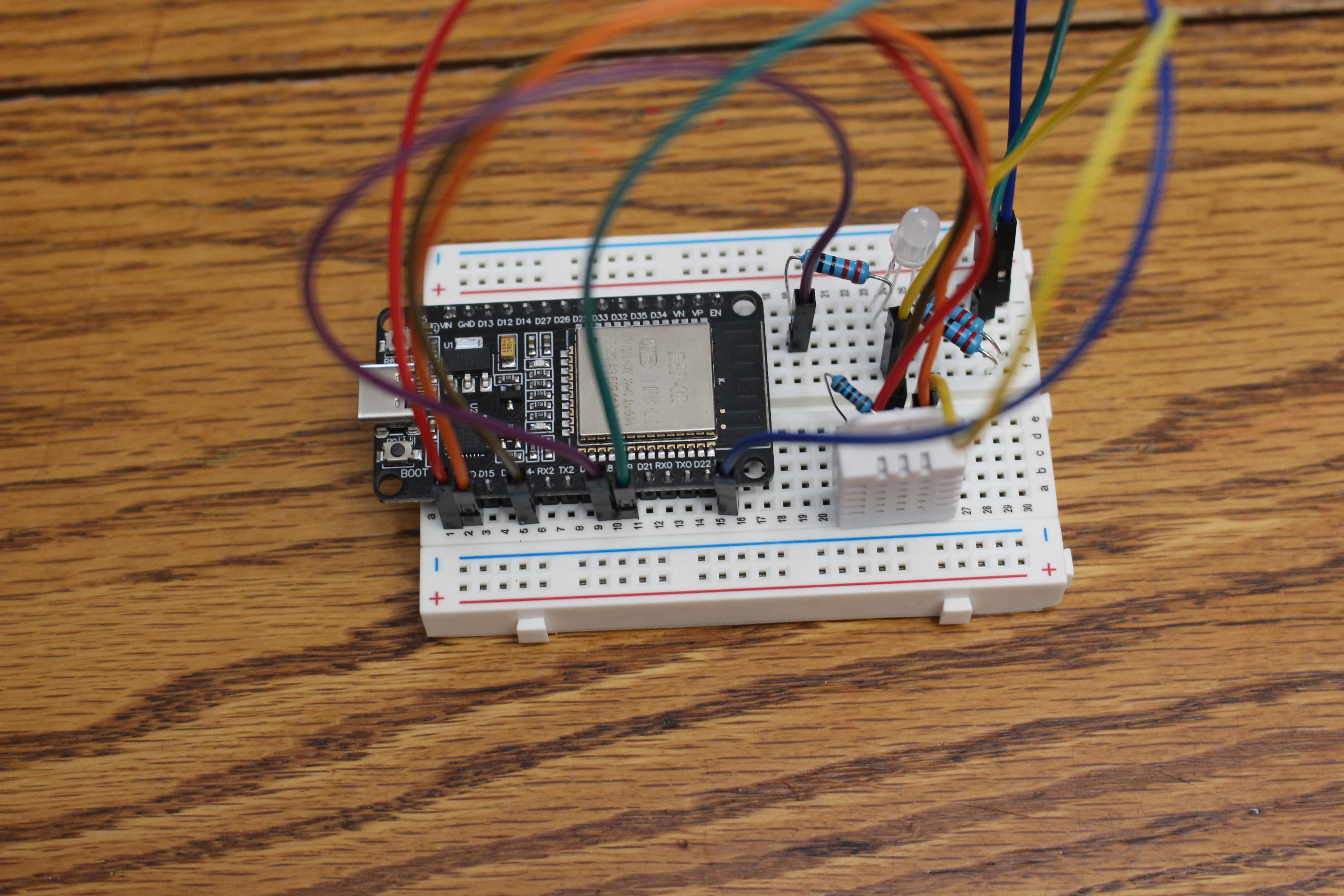
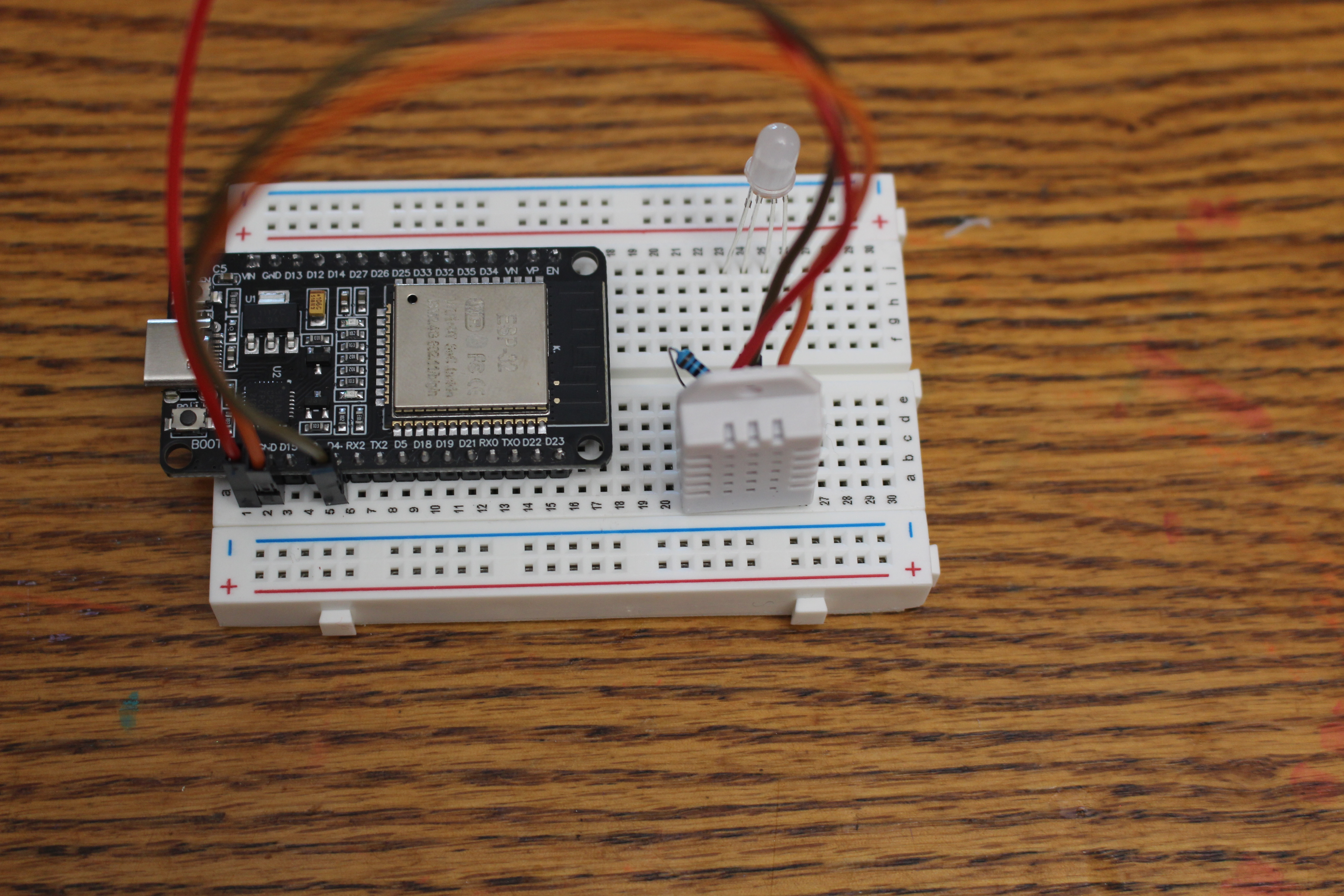
The Full Circuit

Reference schematic. Yours can look different — as long as the connections match!
The Full Circuit
Color Logic (Humidity Mode)
float humidity = dht.readHumidity();

if (humidity < 30) {
  setColor(255, 0, 0);      // Red  - very dry
} else if (humidity < 50) {
  setColor(255, 255, 0);    // Yellow - dry side
} else if (humidity < 70) {
  setColor(0, 255, 0);      // Green - comfortable
} else {
  setColor(0, 0, 255);      // Blue - very humid
}
Humidity is the default — you can change it instantly by breathing on the sensor.
The Color Map
| Humidity | Color | Vibe |
|---|---|---|
| Below 30% | 🔴 Red | Very dry |
| 30–50% | 🟡 Yellow | Dry side |
| 50–70% | 🟢 Green | Comfortable |
| Above 70% | 🔵 Blue | Very humid |
One line switches it to temperature mode instead.
Common Bugs
- Wrong pin numbers (18/19/23 vs the wire)
- Cathode vs anode mixed up (longest leg → GND)
- DHT library not installed
- Read returns
NaN→ check the 10 kΩ pull-up
✅ Big Milestone
Breathe on the sensor → your LED changes color.
🎉 You built a working sensor-driven device.
📋 Quick Quiz!
Checkpoint 5 — Putting It All Together
Join at learning-check.web.app
Enter the code on the screen.
Phone, tablet, or laptop — whatever you've got.
☕ Break — 15 min
Stretch, water, walk around. Almost there.
🔧 Make It Yours
Pick one (or more!) to experiment with.
Easy Tweaks
- Change the humidity (or temp) thresholds
- Pick your own colors for each range
- Print a custom message:
"Maya's room: HUMID" - Make mixed colors — orange, purple, teal
Stretch Goals
- Smooth fade between colors instead of snapping
- Switch from humidity mode to temperature mode
- Watch the value on the Serial Plotter
- Big one: connect WiFi and POST your reading to a webhook
Mixing Colors Cheat Sheet
setColor(255, 128, 0);   // orange
setColor(128, 0, 255);   // purple
setColor(0, 255, 255);   // teal/cyan
setColor(255, 255, 255); // white-ish
🏆 Final Recap Quiz!
One last challenge — everything you built today.
Join at learning-check.web.app and enter the code.
Show & Tell
Who wants to demo their color map?
What You Did Today
- Wired a real circuit on a breadboard
- Uploaded your own code to a microcontroller
- Read a live sensor and drove an LED with PWM
- Built something you understand — and can keep building
Keep Going
Check the Next Steps page for project ideas, and the Glossary if a word was new.
Thank you!